
|
|
|
|
|
|
|
|
|
|
|
KOKO'S STAVE DRUM WITHOUT A LATHE |
|
The Koko Jig Seth's Jig For Cutting The Inside Paul's Jig |
|
PDGood: Sadly, DrumShed appears to be down and all the links to Koko's jig for using a router to do the work of a lathe are broken as a result. Not sure when, if ever, the Shed will be coming back up. However, Koko is in the process of re-constructing a new tuturial. It may take awhile to complete, but here is the start. The Koko Jig Koko: When I started the thread in 2006 I wrote stavedrum wrong and I did that again today for a reason. The search engines need to be redirected to this thread again. First I have to thank many who somehow contributed to the succes of the jig. When I build the jig in 2006 I really had no idea it was that "hot". In all na•vity I solved a problem I had, not realizing it was an answer for so many. It was Lunar who responded within 15 minutes and had recognized the jig's strength. Others have been asking seriously good questions and showing their jigs, discussed improvements and failures too. Many, many thanks to all! I can't reproduce the original thread. Reading that one with today's knowledge shows improvements have been made to the jig that must be included in today's explanation. I am also going to explain how to build it. This is something I always thought of as kind of impossible, since some measurements have to be adjusted to the gear the builder owns [example, the router's base - a Festool has a different sized foot than a Bosch, etc.] I will tell when that is and explain what measurements needs to be taken. I also have decided this thread is not about the jig that is capable of commercialy or industrial interesting results. A jig like that is not in the reach of most people, and you need a completely different level of craftsmanship to accomplish. With this jig, one can build a very, very decent stave drum at relatively low cost. At this very moment the new Koko jig is not 100% ready, so it will take a couple of days for me to finish this thread. My time to spend is reduced dramatically so some patience please! How does the Koko jig work? To understand the working of the jig you need to understand two major things. Basically what you do with a Koko Jig is make a copy of a circle with a router. You copy that circle in your shell. For the outside you use a template, for the inside you copy the outside of the shell itself. But first. Why not use a lathe? Isn't that THE tool to create a cylinder/drumshell? Yes, a lathe is THE tool for making cylinders, no doubt about that. A lathe that is capable of doing a snare drum shell (let alone a bass drum shell) is quite a big lathe, or one that is adjusted for the job and quite expensive too. Totally awesome when you have the space, the money and the skills to use it. Then there is another thing that makes a huge difference between a lathe and a router. With a lathe you spin the material at a certain speed to create the energy for the chisel to do its job. Spinning a raw and unbalanced 14" shell at that speed causes VIBRATION. The centrifugal power of the shell is big and some of you have seen shells "exploding" in the lathe. These were my major concerns at the time when I decided I HAD TO DO a stave shell and lacked the space, the money and the skills to use a lathe. I had to do a stave drum without a lathe. As said above, with a router you can make a copy of a template. One advantage above a lathe is the router doesn't need the material to spin. It spins the chisel and actualy needs the material to move slowly for an accurate cut. (Actually, I think a lathe is the only powertool that moves the material at high speed to create the energy to cut it). Understanding these principles was the start of the koko jig. Slowly moving the raw and unbalanced shell stopped the need of controlling the vibrations. Using a power chisel called a router helped control a clean and easy cut, and a template controlled the circle. Why not use a centre axle? Good question! That is actually what I do in the jig I use for Signature Drums. But, that comes with other problems and solutions. The Koko jig is your perfect solution for DIY drum building, given that you pay attention to detail and accuratly cut the template. I will explain how to cut a template later on this thread about the stavedrum without a lathe, or Koko jig. (Yep, I am feeding the search engines). 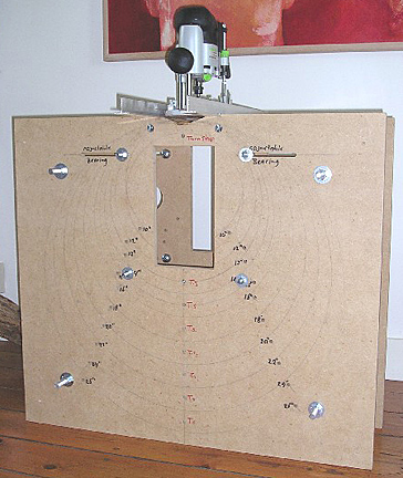 In the first picture you see the original Koko jig, and you can see the template resting on bearings. The bearings allow the template to rotate. You also see the router on sliding bars, hanging above the space where normally the shell should be. (I left the shell out, because that gives clearance to actualy see what I mean). And you see the bit, lowered to the position where it would cut the shell. Now imagine what happens when you slowly rotate the template. ........Exactly, the routerbit starts to cut the shell, copying the template! This is where the sliding bars come in handy. The sliding bars are the bridge for the router to cross, and while the router is cutting/copying the template AND crossing the bridge it will create a cylinder. Read; a drum shell! There are three things important for the sliding bars. They need to be straight. When they are bent or flexed, the router will follow the bend and will copy that in the shell too! They must be strong enough to carry the load and not bend/flex under the pressure that you use to hold the router in place. Next the slidingbars need to be parallel to the templates. I will explain how you check for that later in the thread about the Koko jig. 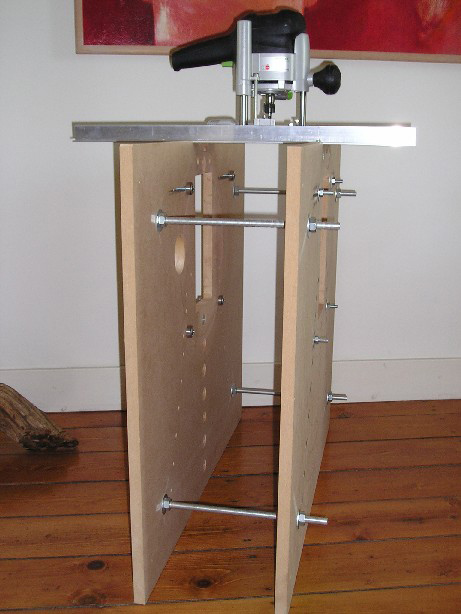 Second picture shows the original stave drum without a lathe jig, showing how to cut the inside. The shell is represented by the circles. Basically the only difference is the place of the router (inside the shell). You now copy the shell, being its own template. (And yep, if you have read the old thread at DrumShed there is a difference here. Using the jig as much as I did learned the circles are not necassery for cutting the inside. Remember the shell of 1.4mm thickness between re-rings I did? That didn't need the extra strength either.) 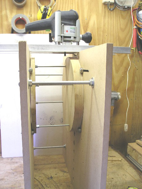 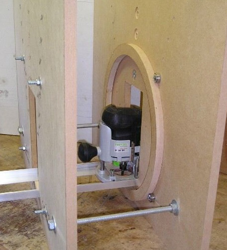 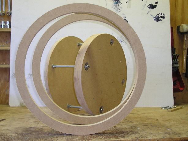 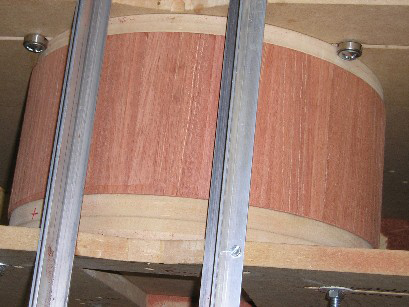 |
|
Paul Wheatley's Jig |
|
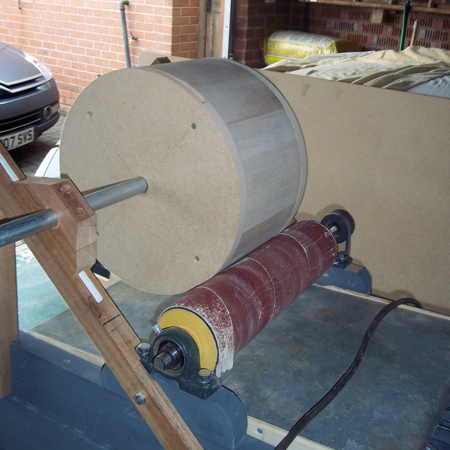
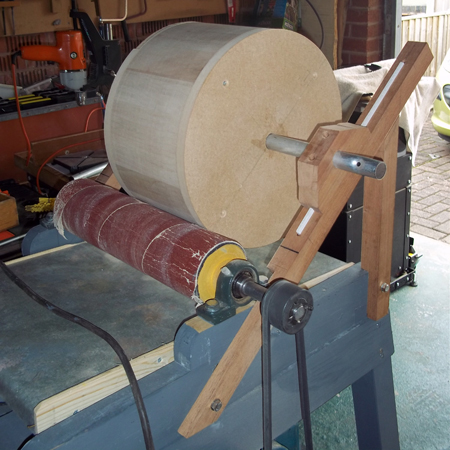
Paul: Working on a 14 x 7 beech snare to be finished in blue burst stain. I was going to lathe the outer face on a home built lathe, but I read a few horror stories about drums exploding under the forces generated by spinning them fast enough to turn. I built myself a thickness sander earlier this year, and adapted this as shown in the photos to shape the outside. It's fairly simple, but works well. I clamped the sliding units to the rails, and used a pair of clamps as stops. I will refine this with adjustable stops if/when I build another drum. I also need to sort a dust collection hopper so I can connect my Shop Vac. I fixed the drum to the axle by gluing some temporary blocks inside the drum, and screwing the mdf circles to these. There are no bearings, just a tight fit hole in the mdf. Again, as the rotation speeds are slow this worked fine for me, but bearings would be a useful add, if I were building a lot of drums. Running 60 grit on the sanding drum, this is a fairly quick operation and the drum itself is turning at very low speed. The ramp is angled to allow me to sand up to a 24" bass drum. The restriction with this set up is depth, which is about 16". PDGood: Hope you don't mind a few questions, Paul. How are you going to remove the temporary blocks glued to the inside of the shell? What turns the drum? By hand? What is meant by: "I clamped the sliding units to the rails, and used a pair of clamps as stops."? I didn't see anything that really looked like clamps or sliding units. Can you clarify a bit please? Thanks. Paul: I only put the temporary blocks in with a little bit of wood glue (I use Tightbond) and minimal clamping pressure until the glue had reached initial set, then left it a few days until time allowed me to do some more work on the drum. This was deliberate, as I was not looking for a permanent bond. I removed them with a chisel and a few taps of the mallet. They actually came off very easily in the end. Because I knew I was going to have to round the inside of the drum out, my only concern was not to split too much (or any) wood off the shell. I turned the drum by hand. I didn't have too much to take off in the end and so it probably took me about half an hour of sanding. I don't see any need to change this as it worked perfectly well, slowly turning the drum in the opposite direction to the sander's rotation. To explain the clamping it is probably easiest to describe the set up in a little more detail. The rails are simple square section timber with the upright mortised into the sloping rail. They were made as accurately as possible and when I glued and clamped the mortises, I dry clamped the two sides together to make sure they were the same. I used a winding rod across the rails and the sanding drum itself to make sure everything was level and parallel. I routed the tops of the rails and set a tongue into them, and grooved the axle mounts to act as a guide and stop the mounts from slipping off the rails. I was concerned about the axle mounts lifting off the rail whilst sanding, so I used small G clamps to clamp the mounts on to the sliding rail. To make sure I did not over sand the drum by pushing it too close to the sander, and also insure I got things as close to true as possible I use another pair of clamps (one per rail) to act as dead stops for the axle blocks. It was a bit crude, but I found everything worked fine by gently tapping the axle blocks down the ramps until I touched the stops. There are lots of ways I could improve the setup. I could put a bracket on to the axle blocks that wrapped around the rails with roller bearing on the bottom to hold them on to the rails. If I had a drill press I could possibly put a tube through the axle blocks and mount a bar on brackets to the rails instead of the tongue and groove. With a bit of ingenuity you could possibly use a threaded rod in place of a bar so that you could screw the drum against the sander. It would be easy to screw an angle bracket on to each rail with a bolt screwed through to act as a dead stop for the axle blocks. This would provide for fine adjustment to shell/sander spacing and alignment. I think, as with all DIY stuff, it's a case of coming up with things that work without the huge outlay of buying professional machines. As we ramp up production, we develop more permanent and refined solutions. I did look at the Koko jig and think it works really well, but to make one that would take all drum sizes, means a big rig (it would have to be near 26" tall to take a 24" bass drum. I simply do not have the room in my garage work shop, so adapting the sander I already have made more sense. I have a much simplified version of the Koko's style jig for routing the inside, and attach a picture. Again, it's small, simple, and cheap to make, but works with a little care and patience. 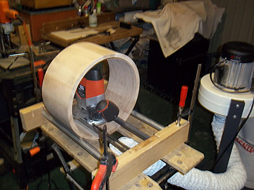 Reading some other sections of the site, there is a lot of talk about getting the chamfers on the staves with table saws and or routers. This is where I am lucky with the kit I have for guitar building. I have a good planer thicknesser with an adjustable fence so I was able plane the chamfers on to my stock very accurately before cutting the staves to length. PDGood: Great info, Paul. |